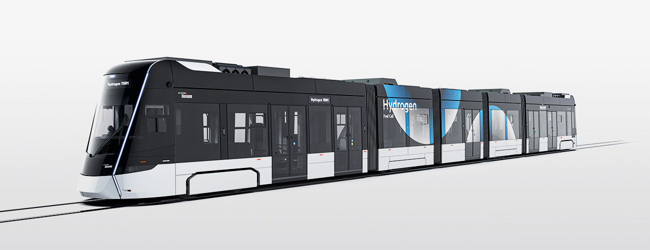
Fuel cell propulsion system is operated by electrical energy generated by the fuel cell system. The hydrogen fuel cell tram is equipped with a low-floor articulated vehicle, which provides better passenger convenience while getting on and off. The height of the floor is only 350mm, allowing wheelchairs and strollers get on and off easily via a manual ramp. Thus, it also reduces the time it takes to pick up passengers at the station.
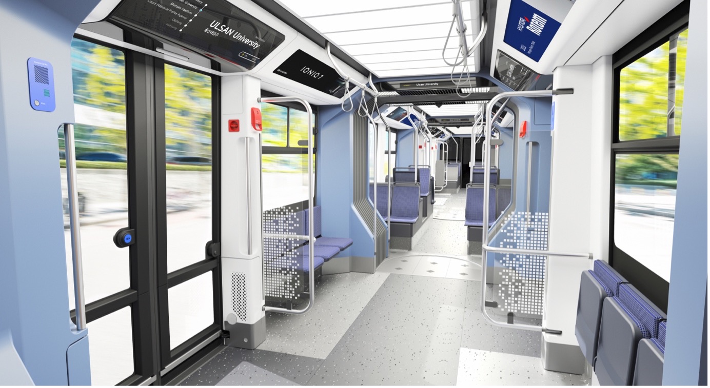
The driver’s seats are provided at the ends of both vehicles to enable driving in both directions. In addition, five sliding plug double leaf doors were installed on the left and right sides of the vehicle. The two-component passenger protection system operates independently and improves safety by informing passengers of the operation of the door through visual and sound devices.
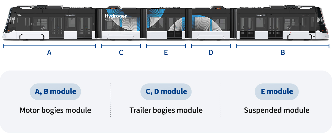
The driving system of the hydrogen fuel cell tram is excellent in energy efficiency by applying the PMSM (Permanent Magnet Synchronous Motor) motor. The outer tram module is supported by a motor bogie, and the two intermediate modules are supported by a trailer bogie. One suspended module is placed between the intermediate modules.
Components of Fuel Cell System
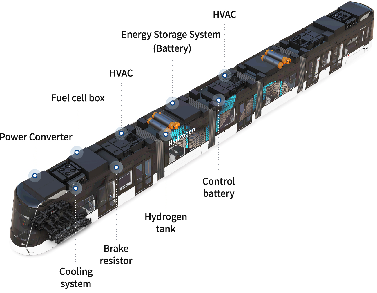
The fuel cell system of the hydrogen fuel cell tram consists of PMC, FDC, hydrogen tank, energy storage system, cooling system and propulsion system. The figure below shows only one of the two fuel cell systems applied to the hydrogen fuel cell tram.
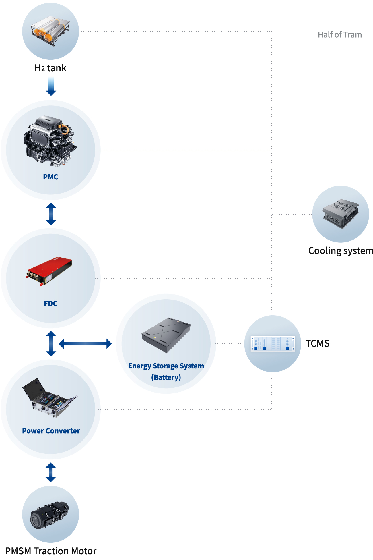
Two fuel cell boxes are installed in the hydrogen cell tram, and the fuel cell box consists of PMC, FDC, pipes to produce hydrogen and silicon hoses to cooling PMC and FDC. The fuel cell box supplies electric energy to the traction inverter and the auxiliary power converter, and each power source including an energy storage system and a hydrogen tank is completely separated for redundancy. All equipment is also controlled and monitored by the TCMS.
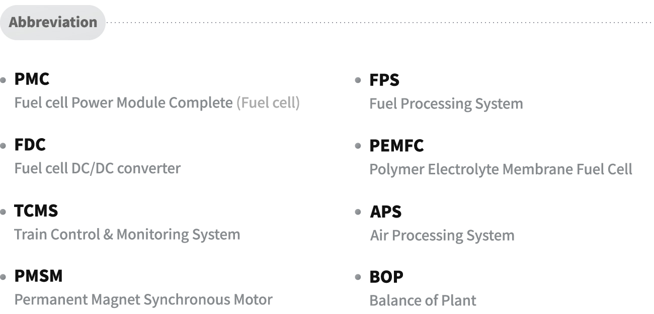
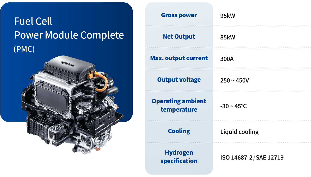
Fuel Cell Power Module Complete (PMC)
A fuel cell is an electrochemical cell device that converts hydrogen and oxygen into electrical energy through a pair of a reduction-oxidation reaction. Fuel cells continuously generate electricity as long as hydrogen and oxygen are supplied. The PEMFC (Polymer Electrolyte Membrane Fuel Cell) type fuel cell applied to hydrogen fuel cell trams was first applied to automobiles (cars, buses, trucks, etc.) and has proven its performance. The fuel cell Power Module Complete (PMC) consists of BOPs (Balance of Plant) such as APS, FPS, humidifier, stack cooling pump, air compressor, and hydrogen sensor.
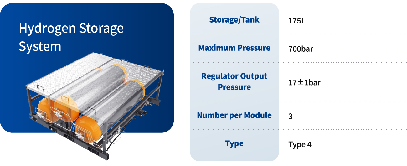
Hydrogen Storage System
The hydrogen fuel cell tram is equipped with two hydrogen storage tank modules. The hydrogen storage tank module consists of a hydrogen tank complete, frame, solenoid valve, end plug, high/medium pressure sensor, regulator and manifold, and hydrogen sensor, and etc. One hydrogen storage tank module will be equipped with three high-pressure tanks (700 bar) with an internal volume of 175L.
It has a structure in which the receptacle and the IR sensor located inside the fuel door are mounted on a single bracket. An infrared communication emitter is installed in the receptacle, and the hydrogen management unit (HMU) uses each sensor signal to calculate the remaining fuel and implements the logic of preventing fuel cell start-up while hydrogen is charged. It also communicates with charging stations in real time when charging hydrogen.
The parts related to the hydrogen storage tank withstand 700 bar pressure and use materials that do not cause hydrogen embrittlement. The outer liner of the hydrogen tank was manufactured by highly durable carbon fiber dipped in an epoxy resin and rolled in a twisted state. The inner liner (Type 4) used a plastic liner material.
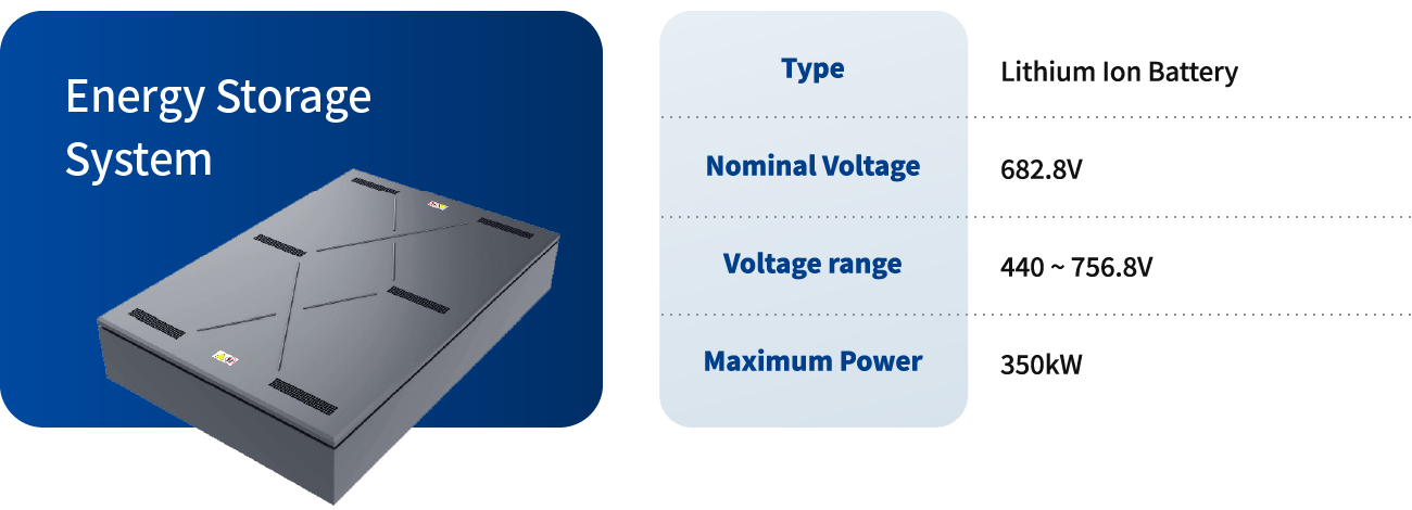
Energy Storage System (Battery)
The electrical energy generated by the fuel cell system is stored in the lithium ion battery of the energy storage system. The maximum output of electric energy generated by the fuel cell system does not reach the maximum output required for operating the hydrogen fuel cell tram. At this time, the insufficient output supplies the electric energy stored in the energy storage system to the traction inverter and auxiliary power converter. In the regenerative braking mode, the output power of the fuel cell system is minimized, and the electrical energy generated during regenerative braking is stored in the energy storage system.
Cooling Unit
An integrated liquid cooling system that effectively cools heat generation is applied to the hydrogen fuel cell tram. A fuel cell is an energy conversion equipment that generates electricity through a chemical reaction between hydrogen as a fuel and oxygen as an oxidizing agent. In this way, not only power but also heat is generated when converted into electrical energy. In addition, heat is generated during operating in BOP and FDC, which are related components that help operate fuel cells. Additionally, traction inverter and auxiliary power supply system generate heat as well.
The integrated liquid cooling system has increased cooling efficiency by integrally managing the heat generation of various systems.

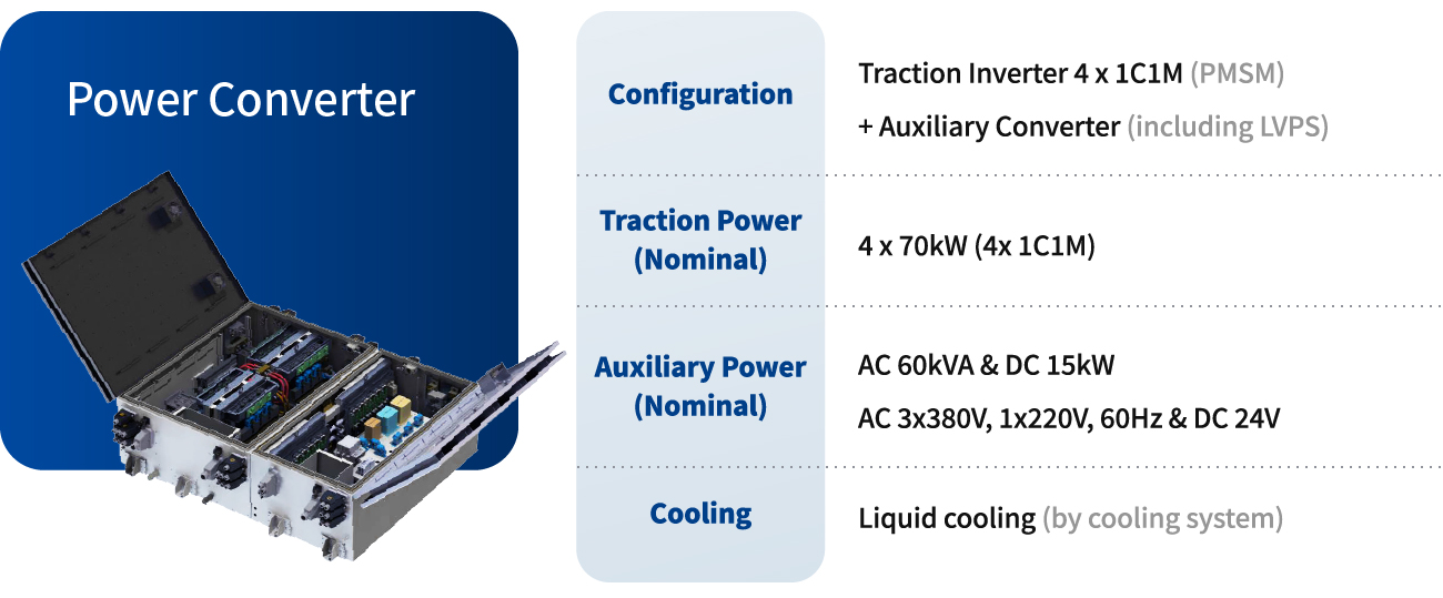
Power Converter
The propulsion system of the hydrogen fuel cell tram is the latest system to which the PMSM(Permanent Magnet Synchronous Motor) as a traction motor is applied. The power converter consists of a traction inverter, an auxiliary converter and a braking resistor. It is installed on top of modules A and B. Each traction inverter consists of four independent traction inverter modules that supply power to one traction motor (PMSM). The auxiliary converter is an equipment that converts the high voltage generated in the fuel cell into an auxiliary voltage of AC 3x380V/60Hz (including AC 1x220V) and DC 24VDC.
The advantages of the hydrogen fuel cell tram’s power converter are as follows.
1. Reduce size and weight by making traction inverter and auxiliary power converter into an all-in-one box
2. Reduce size and weight as power modules, chokes, and transformers water cooling system
3. Apply PMSM traction motors with a high efficiency of 97% or more
4. Reduce wheel maintenance cost by separately managing wheel diameter in 1C1M (one traction inverter module controls one motor) method. Improve ride comfort with separate wheel slip/slide controls.
5. Reduce maintenance cost by applying PMSM
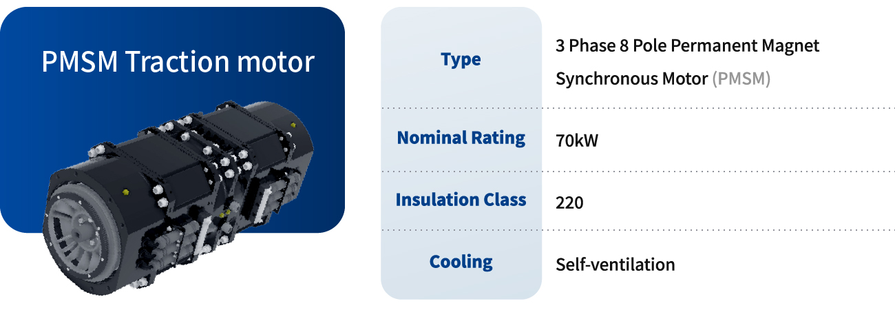
PMSM Traction motor
A total of four PMSM are installed for each wheel per motor bogie. It is powered by electrical energy transmitted by the traction inverter. The traction force generated by the PMSM is transmitted to the driving gear unit through coupling. A gear coupling with excellent flexibility is applied to the gear unit of the PMSM.